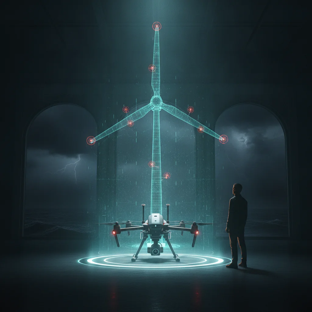
Quick answer: A drone LiDAR survey point cloud measures shape to about 2 to 5 cm vertically, or 1 to 2 cm with survey-grade RTK/PPK, which suits terrain, towers and site baselines. Blade defects like leading edge erosion and trailing edge cracks start below 1 mm, so blade inspections in Taiwan and Japan need close-range zoom photos.
Taiwan wind blades: what a drone LiDAR point cloud can't see
A drone LiDAR survey point cloud measures shape to about 2 to 5 cm vertical accuracy, according to SPH Engineering's UgCS guidance, and 1 to 2 cm with survey-grade RTK/PPK processing. The blade damage that matters on Taiwan and Japan wind farms starts much smaller: leading edge pitting, hairline trailing edge cracks, a scorched lightning receptor. On blades, LiDAR answers geometry questions. A zoom camera answers damage questions.
I fly both. In Taiwan I run solar farm and mapping missions on the DJI Matrice 300, 350 and 400 and the Matrice 4 Enterprise, and I inspect wind turbine blades onshore and offshore. One mistake keeps showing up in scopes: a buyer asks for LiDAR on a blade job because it sounds more precise. It is precise, just at the wrong scale for a blade.
What does a drone LiDAR point cloud actually measure?
It measures distance. A sensor like the DJI Zenmuse L2 on a Matrice 350 RTK fires laser pulses, records several returns per pulse, and fuses them with RTK position and IMU attitude into millions of XYZ points.
That works very well for terrain under vegetation, cut and fill volumes, structure positions, and any job where the unit of measure is the centimetre. On a hillside solar site in Taiwan, one LiDAR flight gives me the bare ground model for drainage and row grading, which photogrammetry struggles with once grass and shrubs cover the slope.
Each point carries a position, an intensity value, and sometimes RGB colour borrowed from a camera. What it can't carry is surface texture at crack scale. On a normal mapping flight the points sit centimetres apart, so a 0.5 mm crack falls between them and the cloud never registers it.

Which blade defects matter most in Taiwan and Japan?
The defect classes are the same worldwide. Local weather decides which ones grow fastest.
- Leading edge erosion. Rain and salt spray at tip speeds of roughly 80 to 90 m/s strip the coating, then the laminate. In the Taiwan Strait, the northeast monsoon from about October to March does most of this work.
- Lightning damage. Burnt receptors, tip blowouts, delamination near the tip. Japan's Sea of Japan coast, Akita included, gets winter lightning, which is known for high-energy strikes on tall structures.
- Trailing edge cracks and bond line splits. Often found around maximum chord. These are structural, and they grow under fatigue loading.
- Laminate cracks, delamination and blisters. Sometimes visible only as a faint line or a change in surface sheen.
- Coating damage and contamination. Gelcoat chips, oil or grease streaks from the hub, insect and salt build-up.
- Impact damage after typhoons. Debris strikes and edgewise cracking after extreme loads.
Most operators grade each finding on a 1 to 5 severity scale, from cosmetic to stop the turbine. Every one of those grades depends on seeing the surface at millimetre resolution, and that's why the camera does the blade work.
Where does LiDAR still earn a place on a wind farm?
LiDAR earns its flight time wherever the question is about position, shape or ground. On a wind project that comes down to 4 jobs.
- Onshore site baselines. Terrain, access roads, crane pads and slopes around foundations, flown once at commissioning and again after major storms to check for movement.
- Tower and structure geometry. Verticality, transition piece position, clearances around the base.
- Blade shape baselines. A point cloud of a parked rotor gives a reference for deformation or tip position, as long as the blade is locked and the scan is repeatable.
- A coordinate frame for defects. A 3D model lets you say a crack sits 41 m from the root on the trailing edge of blade B instead of somewhere near the tip. A textured photogrammetry model gives you the same frame, and that's the route I use in my turbine 3D work.
There's one catch with photogrammetry on blades: white, featureless composite gives the software few tie points, so the model can warp. LiDAR doesn't care about texture. On a clean blade, a LiDAR scan for geometry plus close-range photos for damage can beat either method alone.
LiDAR, zoom photos or photogrammetry: which one answers which question?
Pick the method by the question you need answered. The sensor comes after that.
| Question | LiDAR point cloud | Close-range zoom photos | Photogrammetry model |
|---|
| Is there a hairline crack on the trailing edge? | No, points too far apart | Yes, at about 1 mm per pixel or finer up close | Partly, depends on source photos |
| How severe is the leading edge erosion? | No | Yes | Partly |
| How far from the root is the defect? | Yes | Only with clean metadata | Yes |
| Has the ground around an onshore pad moved? | Yes | No | Yes, on open ground |
| What's under the vegetation on a solar slope? | Yes, with multiple returns | No | No |
| Can it handle a white, featureless blade? | Yes | Yes | Often struggles |
On blade jobs my default is a close-range photo pass with the Matrice 4 Enterprise tele camera or a zoom payload on the Matrice 350 RTK, then a photogrammetry model if the client wants 3D. LiDAR goes into the scope only when someone has a real geometry question.
How often should wind turbine blades be inspected?
The common baseline is one external inspection per turbine per year, plus event-driven checks. Older blades and exposed sites get more.
| Trigger | Typical timing | What gets captured |
|---|
| Routine external inspection | Once a year per turbine | All 4 sides of each blade, root to tip |
| End of warranty | Months before the OEM warranty expires | Full pass, strict grading, evidence for claims |
| After a typhoon | As soon as sea state and wind allow | Tips, leading and trailing edges first |
| After a lightning alert | When strike sensors or SCADA flag an event | Tip, receptors, nearby laminate |
| Site or structure baseline | At commissioning, then after major events | LiDAR or photogrammetry model |
Offshore Taiwan, the weather sets the calendar. The monsoon closes many crew transfer vessel windows between autumn and spring, so an annual campaign gets squeezed into the calm months. That's the reason I built a go / no-go weather view that CTV captains now test for me. A good inspection plan starts with a realistic count of flyable days.
Japan is earlier in the cycle. The first commercial offshore turbines at Akita and Noshiro ports have been running since around 2022 to 2023, so the first end-of-warranty inspections there are close. Those are the inspections where grading discipline matters most, because the report becomes evidence in a claim against the OEM.
What does the workflow look like, from flight to bilingual report?
The flight takes hours. Without automation, the report takes days. So I put most of my engineering effort into the reporting side.
Here's a generic onshore example from Taiwan's west coast. The turbine is stopped, the rotor locked, and the blade being inspected pitched for access. I fly each blade on 4 sides (pressure, suction, leading edge, trailing edge) from root to tip, and every frame gets tagged by blade, side and approximate radius. A full external pass on one turbine usually comes to a few hundred frames.
The agents that build my solar orthomosaics and defect lists then take over, adapted for blades:
- Ingest. Read EXIF and XMP metadata, sort frames by blade, side and radius, and flag gaps in coverage before I leave the site.
- First-pass flagging. A vision model marks candidate defects and crops each one.
- Human review. I accept, reject or regrade every flag. Nothing reaches the report until I've looked at it myself.
- Defect list. The agent drafts one row per finding: ID, blade, side, metres from root, defect class, severity 1 to 5, recommended action.
- Bilingual report. English and 中文 come out of the same source table, so the two versions can't drift apart. Japanese buyers usually want 日文, and that version needs a native reader, since I don't speak Japanese.
- Data handover. Raw frames, crops and any 3D model go to the client in open formats. They paid for the data, so they own it.
Solar uses the same pipeline at a different scale. A hot cell or a failed string shows up at centimetre scale on a thermal orthomosaic, so mapping-altitude flights work. Blades need the drone a few metres from the surface. The automation is identical. Only the capture distance changes.
What should buyers in Taiwan and Japan put in a blade inspection scope?
Write the scope around outputs. Most disputes I've seen in this industry start with a scope that named a sensor and never defined a result.
- A target resolution in mm per pixel on the blade surface, stated in writing.
- Coverage: all 4 sides of every blade, root to tip, with a coverage check in the deliverable.
- A defined 1 to 5 severity scale with example photos, agreed before the first flight.
- Defect location by blade, side and metres from root.
- Raw data ownership, file formats and delivery deadline.
- LiDAR only where a geometric question exists, with the accuracy needed for that question.
- Report languages, and who checks each translation.
Get those 7 lines right and the method choice mostly makes itself. A LiDAR point cloud gives you the site's shape and a camera gives you the blade's condition. The report is where the two become a repair decision.
I set up these capture and reporting pipelines for drone service companies in Taiwan and Japan, in English or 中文. If your team still types up blade reports by hand, start there.
快速解答: 無人機 LiDAR 測量點雲的垂直精度約為 2 至 5 公分,搭配測量級 RTK/PPK 可達 1 至 2 公分,適合用於地形、塔架與場址基準資料。前緣侵蝕、後緣裂紋等葉片缺陷在 1 毫米以下就已開始,因此台灣與日本的葉片檢測需要近距離變焦照片。
台灣風機葉片:無人機 LiDAR 點雲看不見的東西
根據 SPH Engineering 的 UgCS 指南,無人機 LiDAR 測量點雲的垂直精度約為 2 至 5 公分,經測量級 RTK/PPK 處理後可達 1 至 2 公分。然而在台灣與日本的風場上,真正重要的葉片損傷從更小的尺度開始:前緣點蝕、髮絲般的後緣裂紋、燒焦的雷擊接收器。在葉片上,LiDAR 回答的是幾何問題,變焦相機回答的才是損傷問題。
這兩種我都飛。在台灣,我用 DJI Matrice 300、350、400 以及 Matrice 4 Enterprise 執行太陽能電廠與測繪任務,也在陸域與離岸檢測風機葉片。有一個錯誤在工作範疇裡反覆出現:買方因為 LiDAR 聽起來比較精準,就在葉片案件中指定使用 LiDAR。它確實精準,只是用在葉片上尺度不對。
無人機 LiDAR 點雲實際上量測的是什麼?
它量測的是距離。像 Matrice 350 RTK 搭載的 DJI Zenmuse L2 這類感測器會發射雷射脈衝,每個脈衝記錄多次回波,再結合 RTK 定位與 IMU 姿態,融合成數百萬個 XYZ 點。
這非常適合植被下的地形、挖填方量、結構物位置,以及任何以公分為量測單位的工作。在台灣的山坡地太陽能案場,一趟 LiDAR 飛行就能給我用於排水與列間整地的裸地模型;一旦草與灌木覆蓋坡面,攝影測量就很難做到這一點。
每個點帶有位置、強度值,有時還有從相機借來的 RGB 色彩。它無法攜帶的,是裂紋尺度的表面紋理。一般測繪飛行中,點與點之間相距數公分,因此 0.5 毫米的裂紋會落在點與點之間,點雲根本不會記錄到它。
在台灣與日本,哪些葉片缺陷最重要?
缺陷類別全世界都一樣,當地天氣決定哪些長得最快。
- 前緣侵蝕。 在約 80 至 90 m/s 的葉尖速度下,雨水與鹽霧會先剝除塗層,再侵蝕積層。在台灣海峽,大約 10 月至隔年 3 月的東北季風造成了大部分的侵蝕。
- 雷擊損傷。 接收器燒焦、葉尖爆裂、葉尖附近脫層。日本的日本海沿岸(包括秋田)冬季有雷擊,以對高聳結構物的高能量雷擊聞名。
- 後緣裂紋與黏接線開裂。 常見於最大弦長附近。這屬於結構性缺陷,會在疲勞負載下擴大。
- 積層裂紋、脫層與起泡。 有時只呈現為一條淡淡的線,或表面光澤的變化。
- 塗層損傷與污染。 膠衣剝落、從輪轂流出的油或潤滑脂痕跡、昆蟲與鹽分堆積。
- 颱風後的撞擊損傷。 極端負載後的飛散物撞擊與擺振方向(edgewise)裂紋。
大多數業者會以 1 至 5 級嚴重度為每項發現分級,從外觀問題到必須停機。每一個等級都取決於能否以毫米解析度看清表面,這就是為什麼葉片的工作由相機負責。
LiDAR 在風場上還有哪些用武之地?
只要問題與位置、形狀或地面有關,LiDAR 就值得飛。在風電專案中,可歸納為 4 項工作。
- 陸域場址基準資料。 基礎周邊的地形、施工便道、吊車平台與邊坡,在商轉時飛一次,重大風暴後再飛一次以檢查是否位移。
- 塔架與結構幾何。 垂直度、轉接段位置、基座周邊淨空。
- 葉片形狀基準。 停機鎖定轉子的點雲可作為變形或葉尖位置的參考,前提是葉片已鎖定且掃描可重複。
- 缺陷的座標系。 有了 3D 模型,你可以說裂紋位於 B 葉片後緣、距葉根 41 公尺處,而不是「葉尖附近某處」。具貼圖的攝影測量模型也能提供相同的座標系,這也是我在風機 3D 工作中採用的方式。
攝影測量用在葉片上有一個問題:白色、缺乏特徵的複合材料讓軟體幾乎找不到連結點,模型可能因此扭曲。LiDAR 不在乎紋理。在乾淨的葉片上,以 LiDAR 掃描取得幾何、搭配近距離照片判讀損傷,效果可能勝過單用任一種方法。
LiDAR、變焦照片還是攝影測量:哪一種回答哪個問題?
依你需要回答的問題來選方法,感測器是之後的事。
| 問題 | LiDAR 點雲 | 近距離變焦照片 | 攝影測量模型 |
|---|
| 後緣是否有髮絲裂紋? | 否,點距太大 | 是,近距離可達每像素約 1 毫米或更細 | 部分可以,取決於原始照片 |
| 前緣侵蝕有多嚴重? | 否 | 是 | 部分可以 |
| 缺陷距葉根多遠? | 是 | 僅限中繼資料完整時 | 是 |
| 陸域平台周邊的地面是否位移? | 是 | 否 | 是,限開闊地面 |
| 太陽能邊坡的植被下方是什麼? | 是,透過多次回波 | 否 | 否 |
| 能否處理白色、缺乏特徵的葉片? | 是 | 是 | 常有困難 |
在葉片案件中,我的預設做法是先用 Matrice 4 Enterprise 的望遠相機,或 Matrice 350 RTK 上的變焦酬載進行近距離拍攝,客戶若需要 3D 再建置攝影測量模型。只有在有人提出真正的幾何問題時,LiDAR 才會列入工作範疇。
風機葉片應該多久檢測一次?
常見的基準是每部風機每年一次外部檢測,再加上事件觸發的檢查。較老舊的葉片與暴露程度高的場址則需要更頻繁的檢測。
| 觸發條件 | 一般時程 | 拍攝內容 |
|---|
| 例行外部檢測 | 每部風機每年一次 | 每支葉片的 4 個面,從葉根到葉尖 |
| 保固到期 | OEM 保固到期前數個月 | 完整拍攝、嚴格分級、作為求償證據 |
| 颱風過後 | 海況與風況一允許就立即執行 | 優先拍攝葉尖、前緣與後緣 |
| 雷擊警報後 | 雷擊感測器或 SCADA 標記事件時 | 葉尖、接收器、鄰近積層 |
| 場址或結構基準 | 商轉時,以及重大事件後 | LiDAR 或攝影測量模型 |
在台灣離岸,天氣決定行事曆。季風在秋季到春季之間關閉了許多人員運輸船(CTV)的作業窗口,因此年度檢測只能擠進風平浪靜的月份。這正是我建立 go / no-go 天氣看板的原因,目前由 CTV 船長幫我實測。好的檢測計畫,從實際估算可飛行天數開始。
日本則處於週期中較早的階段。秋田港與能代港的首批商業離岸風機約自 2022 至 2023 年起運轉,因此當地第一批保固到期檢測即將到來。這類檢測最講究分級紀律,因為報告會成為向 OEM 求償的證據。
從飛行到雙語報告,工作流程長什麼樣子?
飛行只要幾個小時。沒有自動化,報告就要好幾天。所以我把大部分工程心力都放在報告端。
以下是台灣西海岸一個一般性的陸域案例。風機停機、轉子鎖定,待檢葉片調整到便於作業的角度。我對每支葉片的 4 個面(壓力面、吸力面、前緣、後緣)從葉根飛到葉尖,每張影像都依葉片、面別與大致半徑加上標籤。一部風機完整的外部檢測通常會有數百張影像。
接著由為我產出太陽能正射影像與缺陷清單的代理程式接手,並針對葉片調整:
- 匯入。 讀取 EXIF 與 XMP 中繼資料,依葉片、面別與半徑排序影像,並在我離開現場前標出覆蓋缺口。
- 初步標記。 視覺模型標出疑似缺陷,並逐一裁切。
- 人工審查。 每個標記都由我接受、退回或重新分級。在我親自看過之前,沒有任何內容會進入報告。
- 缺陷清單。 代理程式為每項發現草擬一列:ID、葉片、面別、距葉根公尺數、缺陷類別、1 至 5 級嚴重度、建議處置。
- 雙語報告。 英文與中文版本出自同一份來源表格,因此兩個版本不會出現落差。日本買方通常需要日文版,而這個版本需要母語人士審閱,因為我不會說日文。
- 資料移交。 原始影像、裁切圖與任何 3D 模型都以開放格式交給客戶。資料是他們付費取得的,所有權歸他們。
太陽能用的是同一套流程,只是尺度不同。熱斑電池或故障組串在熱影像正射圖上以公分尺度呈現,所以測繪高度的飛行就足夠。葉片則需要無人機離表面僅數公尺。自動化完全相同,改變的只有拍攝距離。
台灣與日本的買方應該在葉片檢測工作範疇中寫入什麼?
圍繞產出來撰寫工作範疇。我在這個產業看過的多數爭議,都始於工作範疇只指定了感測器,卻從未定義成果。
- 以書面明定葉片表面的目標解析度(每像素毫米數)。
- 覆蓋範圍:每支葉片的 4 個面,從葉根到葉尖,並在交付物中附上覆蓋檢查。
- 明確定義的 1 至 5 級嚴重度並附範例照片,於首次飛行前取得共識。
- 以葉片、面別與距葉根公尺數標示缺陷位置。
- 原始資料所有權、檔案格式與交付期限。
- 只在存在幾何問題時才使用 LiDAR,並註明該問題所需的精度。
- 報告語言,以及由誰審核每一份翻譯。
把這 7 項寫對,方法的選擇大多會水到渠成。LiDAR 點雲告訴你場址的形狀,相機告訴你葉片的狀況。報告則是把兩者轉化為維修決策的地方。
我為台灣與日本的無人機服務公司建置這類拍攝與報告流程,可用英文或中文溝通。如果你的團隊還在手動打葉片報告,就從這裡開始。
Quick answer: ドローンLiDAR測量の点群は、形状を垂直方向で約2〜5 cm、測量グレードのRTK/PPK処理なら1〜2 cmの精度で測定できます。これは地形、タワー、サイトのベースライン計測に適しています。一方、前縁エロージョンや後縁クラックといったブレードの欠陥は1 mm未満から始まるため、台湾と日本のブレード点検には近距離のズーム写真が必要です。
台湾の風車ブレード:ドローンLiDAR点群では見えないもの
SPH EngineeringのUgCSガイダンスによると、ドローンLiDAR測量の点群は垂直精度で約2〜5 cm、測量グレードのRTK/PPK処理を使えば1〜2 cmで形状を測定できます。しかし、台湾や日本の風力発電所で問題になるブレードの損傷は、それよりはるかに小さいところから始まります。前縁のピッティング、後縁のヘアラインクラック、焼け焦げた雷レセプターなどです。ブレードに関して言えば、LiDARが答えるのは形状の問題です。損傷の問題に答えるのはズームカメラです。
私はその両方を飛ばしています。台湾ではDJI Matrice 300、350、400とMatrice 4 Enterpriseで太陽光発電所の点検やマッピングのミッションを行い、陸上と洋上の風車ブレードも点検しています。業務範囲の定義で繰り返し見かけるミスがあります。より精密に聞こえるという理由で、発注者がブレード案件にLiDARを求めてしまうことです。確かにLiDARは精密です。ただ、ブレードにとってはスケールが合っていないのです。
ドローンLiDAR点群は実際に何を測っているのか?
測っているのは距離です。Matrice 350 RTKに搭載したDJI Zenmuse L2のようなセンサーは、レーザーパルスを発射し、1パルスごとに複数のリターンを記録し、それをRTKの位置情報とIMUの姿勢情報と統合して、数百万のXYZ点を生成します。
これは、植生の下の地形、切土・盛土の土量、構造物の位置など、測定単位がセンチメートルである作業では非常によく機能します。台湾の丘陵地にある太陽光発電サイトでは、1回のLiDAR飛行で排水や列の整地に使う地表面モデルが得られます。斜面が草や低木に覆われると、写真測量ではこれがなかなか難しくなります。
各点は位置、反射強度、そして場合によってはカメラから借りたRGBカラーを持っています。持てないのは、クラックのスケールでの表面テクスチャです。通常のマッピング飛行では点の間隔が数センチあるため、0.5 mmのクラックは点と点の間に落ちてしまい、点群には一切記録されません。
台湾と日本で最も重要なブレード欠陥は?
欠陥の分類は世界共通です。どれが最も速く進行するかを決めるのは、その土地の気象です。
- 前縁エロージョン。 約80〜90 m/sの翼端速度で当たる雨と塩分を含んだ飛沫が、まずコーティングを、次に積層材を削り取ります。台湾海峡では、およそ10月から3月にかけての北東季節風がその大部分を引き起こします。
- 落雷損傷。 レセプターの焼損、翼端の破裂、翼端付近の層間剥離などです。秋田を含む日本海側の沿岸は冬季雷が発生する地域で、高い構造物への高エネルギーの落雷で知られています。
- 後縁クラックと接着ラインの剥離。 最大翼弦付近でよく見つかります。これらは構造的な損傷であり、疲労荷重によって進行します。
- 積層材のクラック、層間剥離、ブリスター。 かすかな線や表面の光沢の変化としてしか見えないこともあります。
- コーティングの損傷と汚れ。 ゲルコートの欠け、ハブからの油やグリースの筋、虫や塩分の付着などです。
- 台風後の衝撃損傷。 飛来物の衝突や、極端な荷重を受けた後のエッジ方向のクラックです。
ほとんどの事業者は、各所見を外観上の問題から即時停止が必要なものまで、1〜5の重大度スケールで評価します。どの評価も、表面をミリ単位の解像度で見られることが前提です。だからこそ、ブレードの作業はカメラが担うのです。
風力発電所でLiDARが今でも役立つ場面は?
問いが位置、形状、地面に関するものであれば、LiDARは飛行時間に見合う価値を発揮します。風力プロジェクトでは、それは次の4つの作業に集約されます。
- 陸上サイトのベースライン。 基礎周辺の地形、アクセス道路、クレーンパッド、斜面を、試運転時に一度、そして大型の嵐の後に再度飛行し、変位がないか確認します。
- タワーと構造物の形状。 鉛直度、トランジションピースの位置、基部周辺のクリアランスです。
- ブレード形状のベースライン。 停止したローターの点群は、ブレードがロックされていてスキャンに再現性がある限り、変形や翼端位置の基準になります。
- 欠陥の座標系。 3Dモデルがあれば、「翼端のあたり」ではなく「ブレードBの後縁、根元から41 mの位置にクラックがある」と言えます。テクスチャ付きの写真測量モデルでも同じ座標系が得られ、私の風車3D作業ではこちらの方法を使っています。
ただし、ブレードの写真測量には落とし穴が一つあります。白くて特徴のない複合材ではソフトウェアがタイポイントをほとんど見つけられず、モデルが歪むことがあるのです。LiDARはテクスチャに左右されません。きれいなブレードであれば、形状用のLiDARスキャンと損傷用の近距離写真を組み合わせることで、どちらか一方だけよりも良い結果が得られます。
LiDAR、ズーム写真、写真測量:どれがどの問いに答えるのか?
方法は、答えが必要な問いで選びます。センサーはその後です。
| 問い | LiDAR点群 | 近距離ズーム写真 | 写真測量モデル |
|---|
| 後縁にヘアラインクラックはあるか? | いいえ、点の間隔が広すぎる | はい、近距離なら1ピクセルあたり約1 mm以下 | 一部可能、元の写真次第 |
| 前縁エロージョンはどの程度深刻か? | いいえ | はい | 一部可能 |
| 欠陥は根元からどれくらいの距離にあるか? | はい | メタデータが整っている場合のみ | はい |
| 陸上パッド周辺の地面は動いたか? | はい | いいえ | はい、開けた地面なら |
| 太陽光発電所の斜面の植生の下はどうなっているか? | はい、マルチリターンで | いいえ | いいえ |
| 白くて特徴のないブレードに対応できるか? | はい | はい | 苦戦することが多い |
ブレード案件での私の標準は、Matrice 4 Enterpriseの望遠カメラかMatrice 350 RTKのズームペイロードによる近距離の撮影パスで、クライアントが3Dを望む場合はその後に写真測量モデルを作ります。LiDARを業務範囲に入れるのは、誰かが本当に形状に関する問いを持っているときだけです。
風車ブレードはどのくらいの頻度で点検すべきか?
一般的な基準は、風車1基につき年1回の外部点検と、事象発生時の点検です。古いブレードや風当たりの強いサイトでは、さらに頻度を上げます。
| きっかけ | 一般的な時期 | 撮影内容 |
|---|
| 定期外部点検 | 風車1基につき年1回 | 各ブレードの4面すべて、根元から翼端まで |
| 保証期間終了 | OEM保証が切れる数か月前 | 全面撮影、厳格な評価、クレーム用の証拠 |
| 台風の後 | 海況と風が許し次第すぐに | 翼端、前縁と後縁を優先 |
| 落雷警報の後 | 雷センサーやSCADAが事象を検知したとき | 翼端、レセプター、周辺の積層材 |
| サイトまたは構造物のベースライン | 試運転時、その後は大きな事象の後 | LiDARまたは写真測量モデル |
台湾の洋上では、天候がスケジュールを決めます。秋から春にかけては季節風のために作業員輸送船(CTV)の出航可能な時間帯の多くが閉ざされるため、年1回のキャンペーンは穏やかな数か月に詰め込まれることになります。私がgo / no-goの気象ビューを作ったのはそのためで、今ではCTVの船長たちが試験運用してくれています。良い点検計画は、飛行可能な日数を現実的に数えるところから始まります。
日本はそのサイクルのより初期段階にあります。秋田港と能代港の最初の商用洋上風車は2022年から2023年ごろから稼働しているため、そこでの最初の保証期間終了点検が近づいています。評価の厳密さが最も問われるのがこうした点検です。報告書がOEMに対するクレームの証拠になるからです。
飛行からバイリンガル報告書まで、ワークフローはどうなっているのか?
飛行は数時間で終わります。自動化しなければ、報告書には数日かかります。だから私はエンジニアリングの労力の大半を報告書側に注いでいます。
台湾西海岸の一般的な陸上の例を挙げます。風車を停止し、ローターをロックし、点検するブレードをアクセスしやすい角度にピッチさせます。各ブレードを4面(圧力面、負圧面、前縁、後縁)について根元から翼端まで飛行し、すべてのフレームにブレード、面、おおよその半径位置のタグを付けます。1基の外部点検を一通り行うと、通常は数百フレームになります。
その後は、太陽光発電のオルソモザイクと欠陥リストを作っているエージェントを、ブレード向けに調整して引き継がせます。
- 取り込み。 EXIFとXMPのメタデータを読み取り、フレームをブレード、面、半径位置で並べ替え、現場を離れる前に撮影範囲の抜けを検出します。
- 一次フラグ付け。 ビジョンモデルが欠陥候補にマークを付け、それぞれを切り出します。
- 人によるレビュー。 すべてのフラグについて、私が採用、却下、または再評価します。自分の目で確認するまで、何も報告書には載りません。
- 欠陥リスト。 エージェントが所見ごとに1行ずつ下書きします。ID、ブレード、面、根元からの距離(m)、欠陥分類、重大度1〜5、推奨対応です。
- バイリンガル報告書。 英語版と中文版は同じ元データの表から出力されるため、2つの版の内容がずれることはありません。日本の発注者は通常日本語版を求めますが、私は日本語を話せないため、その版にはネイティブによる確認が必要です。
- データの引き渡し。 生のフレーム、切り出し画像、3Dモデルがあればそれも、オープンなフォーマットでクライアントに渡します。データの対価を払ったのはクライアントなので、所有者もクライアントです。
太陽光発電でも、スケールが違うだけで同じパイプラインを使います。ホットセルや故障したストリングは熱画像オルソモザイク上でセンチ単位で現れるので、マッピング高度での飛行で十分です。ブレードでは、ドローンを表面から数メートルまで近づける必要があります。自動化は同じです。変わるのは撮影距離だけです。
台湾と日本の発注者は、ブレード点検の業務範囲に何を書くべきか?
業務範囲は成果物を軸に書いてください。この業界で私が見てきた紛争の多くは、センサーを指定しただけで結果を定義していない業務範囲から始まっています。
- ブレード表面での目標解像度(1ピクセルあたりのmm)を書面で明記する。
- 撮影範囲:すべてのブレードの4面すべてを根元から翼端まで、成果物に撮影範囲の確認を含める。
- 例示写真付きの1〜5の重大度スケールを定義し、最初の飛行前に合意する。
- 欠陥の位置をブレード、面、根元からの距離(m)で示す。
- 生データの所有権、ファイル形式、納期。
- LiDARは形状に関する問いがある場合のみとし、その問いに必要な精度を明記する。
- 報告書の言語と、各翻訳を誰が確認するか。
この7行を正しく書けば、方法の選択はほぼ自然に決まります。LiDAR点群はサイトの形状を、カメラはブレードの状態を教えてくれます。その2つが修理の判断に変わる場所が報告書です。
私は台湾と日本のドローンサービス会社向けに、こうした撮影と報告のパイプラインを英語または中文で構築しています。もしあなたのチームがまだブレードの報告書を手で打ち込んでいるなら、そこから始めましょう。
Frequently asked questions常見問題よくある質問
Can a drone LiDAR point cloud detect wind turbine blade cracks?Can a drone LiDAR point cloud detect wind turbine blade cracks?Can a drone LiDAR point cloud detect wind turbine blade cracks?
Usually not. Drone LiDAR is accurate to about 2 to 5 cm, or 1 to 2 cm with survey-grade RTK/PPK, and points on a mapping flight sit centimetres apart. Blade cracks and early leading edge erosion start below 1 mm, so they need close-range zoom photos at about 1 mm per pixel or finer.Usually not. Drone LiDAR is accurate to about 2 to 5 cm, or 1 to 2 cm with survey-grade RTK/PPK, and points on a mapping flight sit centimetres apart. Blade cracks and early leading edge erosion start below 1 mm, so they need close-range zoom photos at about 1 mm per pixel or finer.Usually not. Drone LiDAR is accurate to about 2 to 5 cm, or 1 to 2 cm with survey-grade RTK/PPK, and points on a mapping flight sit centimetres apart. Blade cracks and early leading edge erosion start below 1 mm, so they need close-range zoom photos at about 1 mm per pixel or finer.
When is LiDAR worth paying for on a wind or solar project?When is LiDAR worth paying for on a wind or solar project?When is LiDAR worth paying for on a wind or solar project?
When the question is about ground or geometry: onshore terrain and crane pads, slope movement, tower and structure position, blade shape baselines, or ground under vegetation on a hillside solar site. For surface damage on blades or panels, cameras and thermal sensors do the job at lower cost.When the question is about ground or geometry: onshore terrain and crane pads, slope movement, tower and structure position, blade shape baselines, or ground under vegetation on a hillside solar site. For surface damage on blades or panels, cameras and thermal sensors do the job at lower cost.When the question is about ground or geometry: onshore terrain and crane pads, slope movement, tower and structure position, blade shape baselines, or ground under vegetation on a hillside solar site. For surface damage on blades or panels, cameras and thermal sensors do the job at lower cost.
How often should offshore wind turbine blades be inspected in Taiwan?How often should offshore wind turbine blades be inspected in Taiwan?How often should offshore wind turbine blades be inspected in Taiwan?
The usual baseline is one external inspection per turbine per year, plus checks after typhoons, after lightning alerts and before the OEM warranty ends. In practice the northeast monsoon from about October to March limits vessel access, so campaigns get concentrated in the calmer months.The usual baseline is one external inspection per turbine per year, plus checks after typhoons, after lightning alerts and before the OEM warranty ends. In practice the northeast monsoon from about October to March limits vessel access, so campaigns get concentrated in the calmer months.The usual baseline is one external inspection per turbine per year, plus checks after typhoons, after lightning alerts and before the OEM warranty ends. In practice the northeast monsoon from about October to March limits vessel access, so campaigns get concentrated in the calmer months.
What should a drone blade inspection report include?What should a drone blade inspection report include?What should a drone blade inspection report include?
One row per defect with blade, side, distance from root in metres, defect class, severity on a 1 to 5 scale, a cropped photo and a recommended action. It should also include a coverage check, the raw data delivered in open formats, and versions in each language the operator needs.One row per defect with blade, side, distance from root in metres, defect class, severity on a 1 to 5 scale, a cropped photo and a recommended action. It should also include a coverage check, the raw data delivered in open formats, and versions in each language the operator needs.One row per defect with blade, side, distance from root in metres, defect class, severity on a 1 to 5 scale, a cropped photo and a recommended action. It should also include a coverage check, the raw data delivered in open formats, and versions in each language the operator needs.